

We need to pay more attention to how and why SCMs are used...
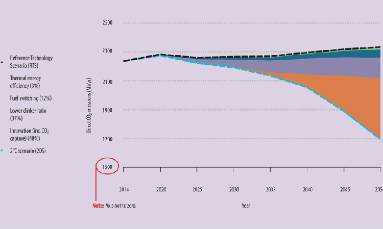
The Cement Sustainability Initiative (CSI) road map shows how CO2 emissions should be improved by 2050 (Figure 1) and has appeared many times in these pages before. Substitution of clinker is the second-largest contributor to reduced emissions, at 37%, after ‘innovative technologies’ - read ‘carbon capture’ - which will be responsible for nearly half of the reduction to the 370 - 420kg of CO2 per tonne of cement target.
However, many producers are still quite far from the 60% clinker factor required by the CSI’s 2 Degree Scenario (2DS). But what if we could push the clinker factor down below 60%? This would likely be far more economical than relying so heavily on ‘innovative technologies,’ as important as these will be. It would also help reduce ongoing production costs per tonne of cement via the optimal use of byproduct materials.
A study by CEMCAP estimates that the leading capture technologies would add at least Euro40/t to the cost of clinker. That is before adding the cost for CO2 compression and pumping for sequestration. If we can make that clinker go further, it will reduce production costs, lower emissions and possibly create happier customers.
How cement works
When looking at how best to use SCMs and non-cementitious fillers, it is important to go back to basics and look at how cement actually works. The active ingredient is calcium silicate hydrate (C-S-H). It’s the glue that holds concrete together. Both the calcium oxide (C) and silica (S) need to be in a reactive form. Different SCMs and fillers bring different chemical elements to the cementitious mix. The traditional focus of SCMs has been to contribute either the C or the S. Slag and type C fly ash add calcium with some silica. They contribute to the formation of C-S-H and contribute to rapid initial hydraulic reactions. Low-calcium fly ash and clays such as metakaolin, are higher in silica, with some alumina. These materials contribute silica to the pozzolanic reactions. These are slower than hydraulic reactions and thus contribute primarily to later strength development.
Maximising SCMs in concrete
60 - 75% plus of the overall mass of a concrete mixture is aggregates. Water accounts for 15 - 20% by mass, with cement / SCMs taking up to 15% and there are also some 5% air voids. At the end of setting the vast bulk of the cement and SCMs have become hydration products, primarily C-S-H, but there can also be a portion of unreacted cementitious material, plus excess water in capillary pores. This can happen even when the cement and SCM chemistry is optimal.
Optimising the particle size of clinker
So, how can we reduce the amount of unreacted cementitious material? We need to pay close attention to the particle size distribution of the ground clinker component, starting with the elimination of clinker particles with diameters greater than 30μm. Particles larger than 30μm will not react fully and thus do not add as much to the strength of concrete as an equivalent weight of smaller particles.
We also need to pay close attention to the very fine material less than 3μm. This material is very reactive, but it needs more water to cover the greater surface areas of these fine particles, thus driving up the water demand of the concrete. While some excess water is needed to separate the particles for flow, it is beneficial to have minimal water left once the reaction to form C-S-H is complete. The more excess water in the cementitious paste, the more voids there will be in the hardened concrete and thus lower strength.
So, both the unreacted, coarse and water hungry, fine clinker particles can reduce overall concrete strength, which is bad for both production costs and CO2 emissions. Both can be replaced with SCMs and other materials.
Optimising the particle packing density
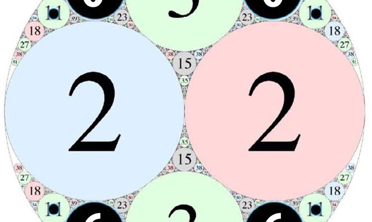
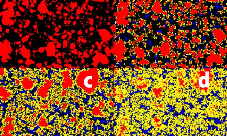
In concrete the largest particles are the aggregates, followed by sand and then cementitious materials. There is a gap between the coarsest cement particles (45μm) and the finest sand (150 - 200μm). We can visualise the inter-particle voids that must be filled by SCMs by looking at Figure 3. The number in each circle shows the ratio of its diameter to the outside circle. Those labelled 2 would typically be fine aggregate and 3 would be sand. However, without optimisation there are no particles corresponding to those labelled 6. Without a fine aggregate to fill this gap, these spaces will be filled with the cementitious paste. There is no strength to be gained from doing this, as the concrete strength is determined by the thinnest layers between aggregates.
Also, if the circles labelled 11 are cement, at around 45μm in diameter, their centres will not react as shown by the black circles. Again, this is a waste of cement, as we will have to rely on smaller cement particles to hold everything together. An ideal situation would be to replace the particles labelled 6 and 11 with a fine aggregate material. By doing this it is possible to reduce the amount of cementitious paste needed.
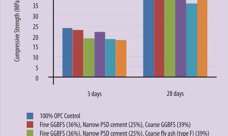
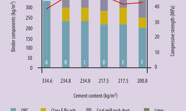
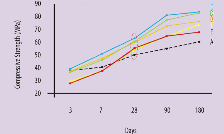
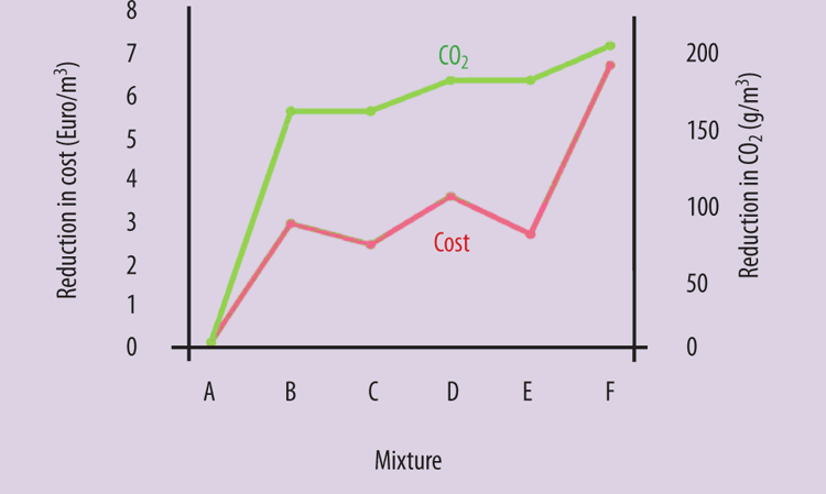
Research at South China University showed that we can achieve acceptable strength development with just 25% clinker in the cementitious mix (See Figure 5). In many cases it appears that the chemical contribution of the coarser SCM is of marginal importance compared to how it fits into the particle size matrix. This is highlighted by the fact that ground limestone acted as a fine aggregate and did not decrease mortar strength appreciably. Meanwhile, the company Roman Cement looked at using coarse fly ash, coal mine rock dust and lime in a number of blends. It was able to reduce the cement content per cubic metre of concrete dramatically (Figures 6 & 7). These mixes showed higher strength over 180 days than a normal cement, sand and aggregate mix, despite using as little as 60% pure cement in the mix, which translates through to cost savings and lower CO2 emissions (Figure 8).
Separate grinding?
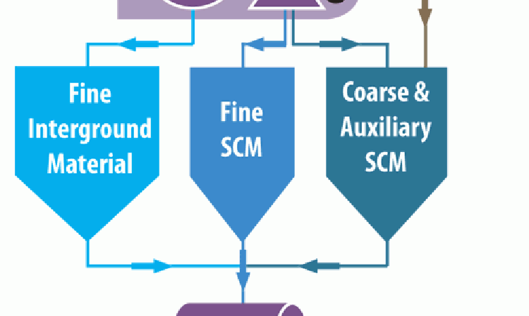
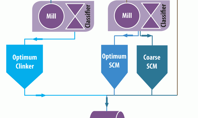
The reactivity of a cementitious material increases with fineness. However, at a given point the extra energy required to grind more finely negates the strength benefits. There exists a sweet spot for each material where the strength improvement versus grinding power is optimised. Crucially, these points do not often overlap for different materials. Therefore, if we seek a high particle packing density, grinding everything together in a single finish mill will not be the best approach. Another way would be to have clinker sent to the finish mill, with the SCM going directly to a classifier. This will enable the separation of a fine and coarse SCM to be mixed with a fine clinker. There is also the option to grind each material in a separate mill, with a blender after grinding to produce the optimum mixture. The possible combinations are endless. Indeed, one cement producer has even added a portion of its raw mix to the finished cement blend because it matched the particle size distribution needed for good packing density. It brought good results and was very inexpensive to do. It is important to understand that the coarser material (>30 μm) is mostly an aggregate that is filling voids in the concrete and does not need to be reactive.
Once any such system is optimised, clinker may become the minor component in the cementitious mix. This may require a new approach to quality control. It could be possible to control this process using the new PGNAA airslide analyser and continuous particle size analyser to ensure the right chemistry and particle size distribution of the blended materials.
Conclusion
Reducing the amount of clinker in cement and concrete mixtures represents a low-cost and relatively low-research option to lower overall CO2 emissions, compared to other technologies. Just by looking at the fundamentals of the reactive particle sizes and packing density allows us to reduce clinker in cement use to levels far below the 60% target given by the CSI 2DS. This may, however, require a far more analytical approach to the grinding and blending of the final cementitious mixtures, with the same level of precision required on the finish side as we currently have on the raw feed side.


